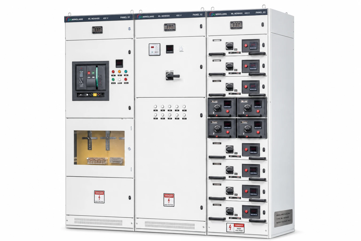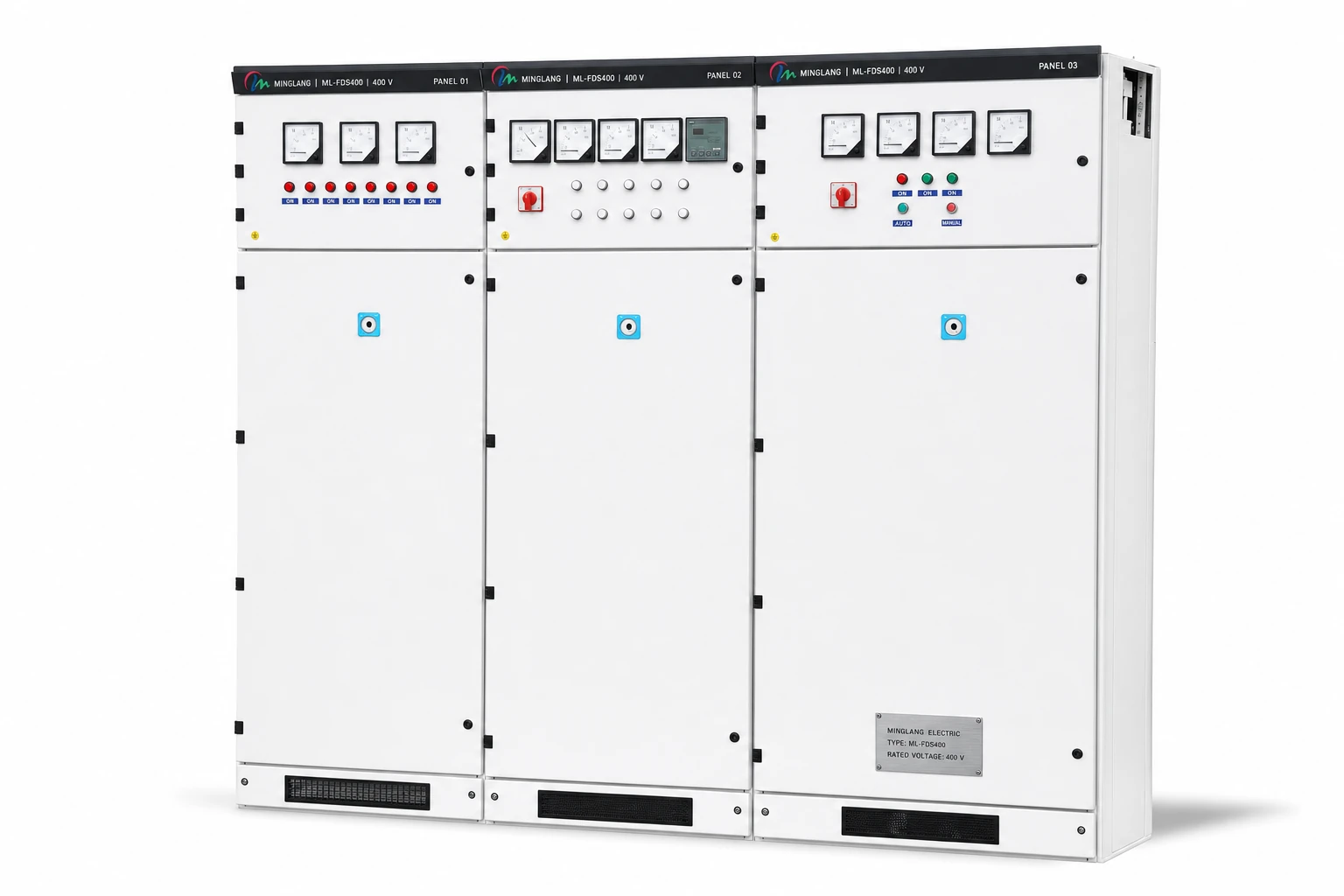
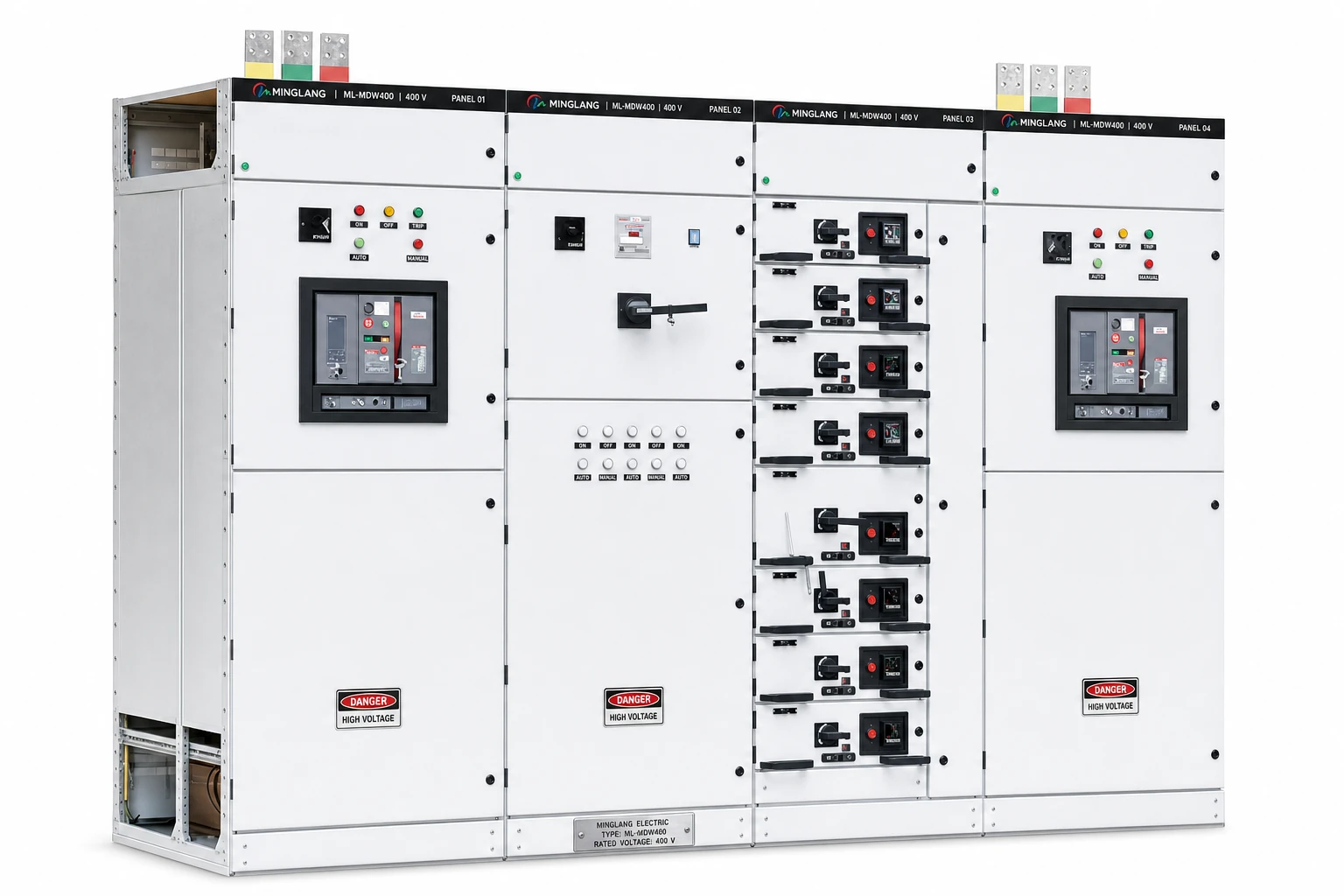
A breaker-brand change does not automatically require every assembly test to be repeated, but it always requires controlled review. The new breaker’s IEC product compliance does not transfer the existing design verification to the completed switchboard. The party responsible for the changed design must identify every affected characteristic and use a verification method permitted for that characteristic by IEC 61439 before the assembly manufacturer releases the revised design.
The procurement question behind “ABB or equivalent”
Specifications often permit an “approved equivalent” or an alternative-brand option. That wording gives commercial flexibility but does not define technical approval. Breakers with the same rated current and headline breaking capacity can differ in:
- power loss and terminal temperature rise;
- short-time withstand and current-limiting behaviour;
- trip-unit functions and protection curves;
- physical size, terminals, clearances and connection hardware;
- accessories, communications, interlocks and door interfaces.
The buyer therefore needs more than a replacement datasheet. The buyer needs a documented effect assessment for the assembly.
Product compliance and assembly verification answer different questions
IEC 60947-2 applies to circuit breakers as products. IEC 61439-1:2020 and IEC 61439-2:2020 address the completed power switchgear and controlgear assembly. Part 1 supplies the general rules; Part 2 supplies the specific requirements for this assembly type. They are applied together.
A circuit breaker report can establish characteristics of the device under its product-standard test conditions. It does not by itself establish that the device, once installed inside a particular compartment and connected to a particular busbar system, will preserve the complete assembly’s temperature rise, short-circuit strength or separation arrangement.
This distinction is central to a responsible substitution review:
| Evidence | Question it can answer | Question it cannot answer alone |
|---|---|---|
| Breaker datasheet | What are the device ratings and available functions? | Does this installation preserve the assembly verification? |
| Breaker product certificate or report | Was the device assessed to its stated product standard and scope? | Will the complete switchboard meet IEC 61439 with this substitution? |
| Original assembly verification | What reference design and conditions were verified? | Does an unassessed change remain within that verified design? |
| Substitution assessment | How does the proposed change affect each relevant assembly characteristic? | It cannot cover items outside its stated evidence and assumptions |
| Routine verification | Was the manufactured assembly checked for the applicable routine items? | It does not replace missing design verification |
Who carries responsibility after a change?
IEC 61439 distinguishes the original manufacturer, responsible for the original design and its design verification, from the assembly manufacturer, responsible for the completed assembly and its routine verification. The same organization may perform both roles. A panel builder may also build within another organization’s verified assembly system.
If the panel builder follows all requirements and instructions issued by the original manufacturer, the original design verifications do not need to be repeated. If it introduces an arrangement outside that verified system, IEC 61439 treats it as the original manufacturer for that alternate arrangement. It must design-verify the affected arrangement and still routine-verify the completed assembly.
The practical questions are:
- Is the proposed breaker already an approved device within the verified assembly system?
- If it is outside the approved system, which verification methods does IEC 61439 permit for each affected characteristic?
- Which characteristics need additional testing or other evidence?
- Who accepts the revised design and controls it through manufacturing?
A purchase-order phrase such as “approved equivalent” should never leave these questions to the production stage.
Seven checks before approving a new breaker brand
1. Confirm the complete device identity
Do not compare only frame size and rated current. Record:
- manufacturer, product family, frame, poles and execution;
- operational/insulation voltages, current, rating plug and loading;
- trip unit, firmware and short-circuit ratings;
- terminals, accessories and communication modules;
- declared ambient and installation conditions.
The approved bill of materials should identify an exact order code or a controlled range. “Brand B 3,200 A ACB” is not a controlled equipment definition.
2. Review power loss and terminal temperature rise
Changing the main device changes compartment heat. Compare data produced under equivalent conditions, including:
- total power loss at the relevant current and loading group;
- terminal temperature rise and the tested conductor/terminal arrangement;
- permitted ambient, mounting orientation, free space and ventilation;
- heat from the trip unit, motor operator and accessories.
The review should preserve the assembly rated current (InA), circuit rated current (InC) and applicable group rated current (Ing). IEC 61439-1:2020 introduced Ing to express how a circuit can carry current while other circuits in the same group are loaded.
IEC 61439-1:2020 gives a specific temperature-rise substitution rule. For a similar device with rated current In not exceeding 1,600 A, a device from another series and from the same or a different device manufacturer may be substituted when its power loss and terminal temperature rise are the same or lower, with both devices tested to their product standards.
That route also requires the physical arrangement within the functional unit to be maintained and prohibits increasing the functional-unit rating. The maintained arrangement includes terminal shields, conductor type, material and connection size, mounting orientation, clearances, ventilation and terminal arrangement.
For any current rating, a same-manufacturer substitution may instead rely on that device manufacturer’s declaration of temperature-rise performance, subject to the conditions in the standard. This only resolves temperature-rise verification. Short-circuit strength and every other affected design characteristic still require separate review.
For a cross-brand device above 1,600 A, equal or lower power loss is useful engineering data, but it does not satisfy that substitution route by itself. The circuit needs a temperature-rise test or a qualifying comparison with a tested reference design under IEC 61439-2.
For high-current assemblies, small differences in device and connection loss can materially change compartment temperature. A simple comparison of rated current is insufficient.
3. Verify short-circuit characteristics as a system
Headline values such as Icu or Ics do not describe every short-circuit characteristic relevant to an assembly.
Check as applicable:
- Icu, Ics, making capacity, Icw and duration;
- peak let-through current, I²t and any back-up combination;
- incoming protection settings and actual fault level;
- busbar, conductor, neutral and protective-circuit duty.
For short-circuit verification by the IEC 61439-1 Table 13 checklist, the protective device is expected to be the same make and series. A different series from the same device manufacturer can be treated as equivalent when that manufacturer declares equal or better performance in every relevant respect, including breaking capacity, limitation characteristics such as I²t and peak let-through current, and critical distances. A breaker from another manufacturer normally fails this checklist item under the international text and needs another permitted verification route, unless a stated national variation applies.
4. Recheck protection selectivity and operating philosophy
Two breakers with equal ratings may use different trip curves, tolerances and settings. Review:
- long-time, short-time, instantaneous and earth-fault functions;
- upstream/downstream discrimination and zone interlocking;
- ground-fault sensors, transformer/motor duty and generator/UPS contribution;
- transfer, load-shedding and arc-energy-reduction logic.
If the project protection study used a manufacturer-specific device model, update it with the proposed device data. Protection coordination and selectivity should meet the user/manufacturer agreement and project philosophy. “Equivalent breaking capacity” does not establish equivalent selectivity.
5. Check terminals, busbars and insulation distances
A new breaker can alter the current path even when it fits within the same nominal compartment width.
Confirm:
- terminal type, material, orientation, pole pitch and bolts;
- busbar overlap, drilling, links and support spacing;
- electrodynamic forces and conductor phase sequence;
- insulation/impulse ratings, clearances and creepage distances;
- barriers, shutters, torque and tool access.
Avoid adapting busbars on the shop floor from a marked-up photograph. The revised connection should be engineered, drawn, approved and released under document control.
6. Recheck mechanical construction and separation
The replacement can affect:
- doors, handles, cradle and racking mechanism;
- service, test and disconnected positions and interlocks;
- shutters, barriers, separation and enclosure IP;
- cable space, maintenance route and structural support.
The new device should preserve the intended operating sequence and access controls. A door that no longer closes with the specified handle fitted is an obvious failure; a reduced clearance behind the breaker can be less visible and equally important.
7. Review auxiliary, metering and communication interfaces
The substitution may change control voltage, coil consumption, contacts or network architecture. Confirm:
- close, trip, undervoltage and motor-charging supplies;
- auxiliary contacts, positions and trip indications;
- PLC/ATS/protection, protocol and gateway interfaces;
- metering, sensors, terminal plans, firmware and point lists.
All affected drawings, cause-and-effect documents and FAT procedures should follow the approved device revision.
Substitution decision table
| Proposed change | Initial risk view | Minimum approval evidence |
|---|---|---|
| Same manufacturer, same exact device and revision | Low, subject to document confirmation | Controlled BOM, current datasheet and assembly-system inclusion |
| Same manufacturer, successor in the same family | Moderate | Manufacturer’s substitution statement plus thermal, short-circuit, dimensional and functional comparison |
| Same manufacturer, different family | Moderate to high | Full effect assessment against the verified reference and additional verification where required |
| Different manufacturer with similar ratings | High | Apply the 1,600 A temperature-rise limit and Table 13 short-circuit restrictions; product certificates alone are insufficient |
| Different frame size or connection orientation | High | Revised busbar and mechanical design, applicable verification, drawings and manufacturing release |
| Different trip unit only | Moderate | Protection-study, control-power, communication and thermal/accessory review |
| Temporary production substitution without revised documents | Unacceptable | Stop release until the change is engineered, approved and recorded |
The table is a screening tool. The actual verification route depends on the assembly, proposed device and applicable project requirements.
Illustrative example: replacing a 3,200 A incomer ACB
Assume an approved LV switchboard design uses a 3,200 A withdrawable air circuit breaker. A different brand is proposed because the original device cannot meet the delivery date. The proposed breaker also states 3,200 A, the required operating voltage and a headline short-circuit rating above the project fault level.
Those values support initial screening. They do not complete approval. Because this is a cross-brand change above 1,600 A, the specific IEC 61439-1 temperature-rise substitution route does not apply; a test or qualifying comparison with a tested reference design is needed. The breaker also fails the same-make condition in the international Table 13 short-circuit checklist.
The technical clarification should still answer:
- Which permitted method will verify assembly temperature rise with the proposed 3,200 A breaker?
- Does its Icw and duration match the busbar and protection-clearing duty?
- Are its peak and let-through characteristics compatible with the verified assembly basis?
- Does the revised trip unit preserve the coordination study?
- How will its terminals connect to the existing busbar without reducing clearance or short-circuit strength?
- Does the new cradle preserve the service, test and disconnected positions and interlocks?
- Do door, shutter, barrier, IP and separation arrangements remain valid?
- Have schematic, terminal, communication, GA, BOM and FAT documents been revised?
If any answer relies on an assumption, record the assumption and the evidence needed to close it before manufacturing release.
What buyers should require in the substitution package
A useful component-substitution submission should include:
- a formal change request with both order codes;
- rated-characteristic, temperature-rise and short-circuit comparisons;
- updated protection study where affected;
- connection drawings and insulation/separation review;
- revised schematics, terminals and communication points;
- the design-verification route and supporting evidence;
- updated BOM, routine-verification and FAT requirements;
- technical and contractual approvals.
The submission should also state what remains unchanged. This helps reviewers distinguish a limited component change from a wider redesign.
Buyer’s approval checklist
- Exact original and proposed order codes are stated.
- Product-standard evidence for the proposed device is available.
- Assembly-verification responsibility is identified.
- Power loss and terminal temperature rise are compared on a consistent basis.
- The 1,600 A limit and same-manufacturer declaration option are applied correctly.
- Icu, Ics, Icw, duration, making and limiting characteristics are reviewed.
- Table 13 same-make/series conditions are checked before claiming short-circuit verification by comparison.
- Protection settings and selectivity are updated where required.
- Terminals, busbars, torque and current-path geometry are approved.
- Clearances, creepage distances and barriers remain acceptable.
- Form of separation, IP and interlocks are preserved.
- Auxiliary supply, wiring, indication and communication are coordinated.
- GA, schematic, terminal, BOM and FAT documents carry the same revision.
- The applicable design-verification route and evidence are recorded.
- No substitution can reach production without approved change control.
Frequently asked questions
Does an IEC 60947-2 certificate make the substitute breaker acceptable in an IEC 61439 switchboard?
It confirms device-level evidence within its stated scope. The completed assembly still requires applicable IEC 61439 design and routine verification, including the effects of installation and connection.
Must the complete switchboard be retested after every breaker change?
Not in every case. Annex D identifies whether testing, comparison with a reference design or assessment is permitted for each characteristic. The original manufacturer for the changed arrangement must document why the selected method covers that change.
Is equal Icu enough for a replacement?
No. Ics, Icw and duration, making capacity, current limitation, protection settings, selectivity, terminal arrangement and assembly short-circuit strength may also matter.
Can a breaker from another manufacturer be approved?
It can be considered. For temperature rise, the specific cross-manufacturer substitution route is limited to similar devices not exceeding 1,600 A and its other conditions must be met. For Table 13 short-circuit comparison, the international text requires the same make and series, with a stated allowance for another series from the same manufacturer. A cross-brand change therefore may require another verification route.
Does a lower power-loss value automatically approve the substitution?
No. For a device up to 1,600 A it is one condition in the temperature-rise substitution route; maintaining the physical arrangement and functional-unit rating is also required. Above 1,600 A, the cross-brand route does not apply. Other design characteristics remain separate in every case.
Who should approve an “equivalent” breaker?
The assembly manufacturer must control the completed assembly. For an arrangement outside the original verified system, it assumes the original manufacturer’s verification responsibility for that change. The project’s contractual reviewer or end user also approves the deviation where required.
Should FAT be changed after a breaker substitution?
Yes, when the device change affects operation, interlocks, protection, indications, communication or documents. FAT remains a project acceptance activity and does not replace missing design verification.
Submit a controlled alternative, not a brand-only substitution
For an international-brand or alternative-brand LV proposal, provide the single-line diagram, fault study, protection philosophy, approved vendor requirements, feeder schedule, ambient conditions, form of separation, IP class, communication requirements and document list. Minglang can then present the proposed BOM, deviations and configuration-specific evidence in one reviewable package.
Source material
References
- IEC, IEC 61439-1:2020 — General rules for low-voltage switchgear and controlgear assemblies.
- IEC, IEC 61439-2:2020 — Power switchgear and controlgear assemblies.
- Siemens, IEC 61439 design verification and routine verification responsibilities.
- Siemens, 3WA and 3WL integration example against IEC 61439 Table 13.
- ABB, Product-specific Emax to Emax 2 migration and temperature-rise comparison.
- Schneider Electric, Original manufacturer, assembly manufacturer and specifier responsibilities.
- Schneider Electric, IEC 61439 support for panel builders.