Choose AFL only when the front and lateral sides are accessible in service and the rear is genuinely inaccessible under the manufacturer’s verified installation conditions. Choose AFLR when personnel can enter a rear aisle or otherwise approach the rear. In both cases, confirm the accessibility type, rated arc-fault current, duration and pressure-relief arrangement. The letters alone do not approve a switchgear room: the final general arrangement must preserve the tested enclosure, clearances and hot-gas path.
What an IAC designation actually tells you
The current IEC reference is IEC 62271-200:2021+AMD1:2024, covering prefabricated AC metal-enclosed switchgear and controlgear above 1 kV and up to and including 52 kV. IAC is an optional classification established by testing a defined assembly under defined conditions. A project designation therefore needs more detail than “arc resistant.”
For example:
IAC A FLR 25 kA 1 s
| Part of designation | Project meaning | What the buyer must verify |
|---|---|---|
| IAC | The tested assembly met the IEC internal-arc criteria for the stated configuration and test conditions | Test report identity, assembly construction, compartments tested and installation arrangement |
| A | Accessibility restricted to authorized personnel | The switchgear is installed in a controlled electrical service location |
| B | Unrestricted accessibility, including areas accessible to the general public | Whether the project location actually requires Type B and whether the offered assembly was tested as Type B |
| F | Protection evaluated at the front | Front operating aisle and doors match the verified arrangement |
| L | Protection evaluated at accessible lateral sides | Lineup ends, side covers, adjacent walls and extensions are addressed |
| R | Protection evaluated at the rear | Rear aisle, rear covers and rear access arrangement are included |
| 25 kA | Rated arc-fault current used for the classification | Available fault duty and the project’s earthing and protection conditions |
| 1 s | Rated arc-fault duration | Total fault-clearing time, including relay operation, breaker interruption and any upstream backup operation |
Accessibility Type A and Type B describe who may approach the equipment; they are not different names for AFL and AFLR. Their IEC test arrangements and indicator positions differ. Type B uses the arrangement for unrestricted public access. A locked Type A enclosure does not become Type B.
Likewise, F, L and R identify the tested accessible sides. They do not describe the direction in which gas is discharged. An AFLR panel may still vent upward into a room, through a top duct, or through an engineered duct to the outside, depending on the tested design.
IAC, arc-flash assessment, LSC and PM/PI answer different questions
These terms are often placed in the same data sheet, but each addresses a separate issue.
| Term | Question it answers | What it does not establish |
|---|---|---|
| IAC | Did a defined switchgear assembly meet internal-arc test criteria at stated sides, current and duration? | Site incident energy, PPE category, safe working distance or every possible internal fault condition |
| Arc-flash risk assessment | What thermal hazard may a worker face for the actual system, protection settings, work task and distance? | IEC 62271-200 classification of the enclosure |
| LSC category | How much of the switchgear can remain energized when an accessible high-voltage compartment is opened under the defined service condition? | Internal-arc performance |
| PM or PI | Are the partitions and shutters between an opened accessible compartment and live parts metal (PM), or is an insulating partition/shutter involved (PI)? | AFL, AFLR, arc-fault current or duration |
An LSC2B-PM assembly supports defined service continuity and uses metal partitions, yet still needs a separately stated IAC classification. An IAC-classified assembly does not automatically have LSC2B-PM construction.
IAC cannot replace an arc-flash study. IEC testing evaluates enclosure behaviour against prescribed criteria. A site study evaluates the electrical system and worker exposure. ABB’s mitigation guidance likewise treats passive enclosure performance, active arc detection and incident-energy reduction as distinct measures.
Select the accessible sides from the real room
Mark every place where an authorized person or member of the public can stand during operation, inspection, testing and maintenance. Then select the IAC sides from that access map.
| Actual installation condition | Minimum classification question | Design action before approval |
|---|---|---|
| Front-operated lineup permanently against a wall, with no energized rear access | Can a verified AFL arrangement cover this installation? | Confirm tested wall clearance, maintenance access and gas exhaust route |
| Free-standing lineup with a rear service aisle | Is the rear included in the classification? | Specify FLR and show the rear aisle on the GA |
| Lineup ends exposed to an aisle | Are both accessible lateral ends covered? | Confirm end-panel construction, side clearances and any future extension arrangement |
| Rear void behind a removable partition or locked door | Could personnel enter while energized? | Treat the rear as accessible unless permanent controls make access impossible |
| Switchgear in or adjoining a public area | Is Accessibility Type B required by the owner, authority or risk assessment? | Do not substitute Type A; confirm a Type B tested configuration |
| Two lineups facing or backing toward each other | Can an arc exhaust from one lineup enter the working aisle or strike the other lineup? | Coordinate aisle width, ducts, relief outlets, walls and the room pressure assessment |
Does back-to-wall installation make AFL sufficient?
It can, for a product verified in that arrangement and a room where the rear remains inaccessible. ABB’s ZX0.2 catalogue gives a product-specific example: its wall-installation configuration is IAC AFL, while its free-standing configuration is IAC AFLR. Both rely on the stated pressure-relief arrangement.
The classification of one physical arrangement cannot be transferred to another without evidence.
Follow the hot-gas path all the way to a safe discharge point
During an internal arc, hot gases and particles follow the path provided by roof flaps, absorbers, a plenum, a rear channel or an external duct. Each option changes the room interface.
The design team should trace this route on the GA:
- faulted compartment and pressure-relief opening;
- internal channel, room volume or external duct;
- terminal discharge point and its exclusion zone.
A beam, cable tray, light, ventilation duct or fire pipe can obstruct a flap or redirect gas toward an aisle. An external outlet can also face a walkway, door or air intake.
Schneider Electric’s MCSeT documents show different ceiling heights and rear clearances for specific internal- and external-exhaust arrangements. They also state that building safety under internal-arc pressure and required room relief openings need separate consideration. The published dimensions belong to MCSeT; ceiling height and civil design remain product-specific.
The room designer should therefore confirm:
- minimum clear height above the completed switchgear, including LV compartments and arc duct;
- obstruction-free space for pressure flaps;
- duct section, supports, bends and route limits;
- outlet location and weather protection;
- allowable pressure load on walls, doors, ceilings and penetrations;
- room pressure-relief openings and fire stopping;
- safe access after an event.
Illustrative room scenario: the rear aisle changes the answer
Consider a nine-panel, 12 kV indoor lineup in a restricted substation. The initial civil drawing shows:
- 21 kA prospective short-circuit current at the MV bus;
- 0.55 s maximum total clearing time for the relevant bus or feeder fault, including breaker interruption;
- a 1,000 mm front operating aisle;
- an 800 mm rear maintenance aisle with a locked access door;
- exposed lineup ends;
- 3,300 mm clear room height;
- a proposed top duct discharging through the external wall.
The locked rear door does not remove the rear from consideration. Authorized personnel can enter, so the selection basis is Accessibility Type A with F, L and R coverage. IAC A FLR 25 kA 1 s would exceed the stated inputs in this simplified example. Approval still requires evidence for the offered assembly and exact duct arrangement.
If the owner deletes the rear aisle, AFL may become feasible only if the product supports front access, the rear becomes permanently inaccessible, the wall clearance matches the verified arrangement and maintenance remains practical. The revised GA must show the duct, cable entries and fixings.
If clearing time rises to 1.2 s or fault duty exceeds 25 kA, the example classification no longer matches. Both changes require technical review.
Procurement and design confirmation table
Issue this information with the enquiry and require the supplier to return evidence against it.
| Required project input | Why it matters | Required supplier response |
|---|---|---|
| System voltage, frequency and earthing method | Defines assembly and fault conditions | Offered ratings and applicable evidence |
| Prospective short-circuit current at the switchgear bus | Establishes the project fault duty | Rated short-time withstand duty and rated arc-fault current, stated separately |
| Maximum clearing time, including backup protection | Checked against arc-fault duration | Assumptions and declared IAC duration |
| Authorized-only or unrestricted access | Selects Accessibility Type A or B | Full IAC designation, not only “arc proof” |
| Accessible front, lateral and rear faces | Selects F, L and R coverage | Marked access diagram and tested arrangement |
| Room plan, section and clear height | Controls aisles, flaps and ducts | GA with minimum clearances |
| Arc-exhaust concept and proposed outlet | Controls the hot-gas route | Duct/absorber option, limitations, supports and outlet exclusion zone |
| Cable entry, penetrations and HVAC | Can obstruct the exhaust path | Coordinated interface drawing |
| Lineup, end covers and future extension | Evidence depends on construction and boundaries | Applicability statement for the offered lineup |
How to review a Minglang reference configuration
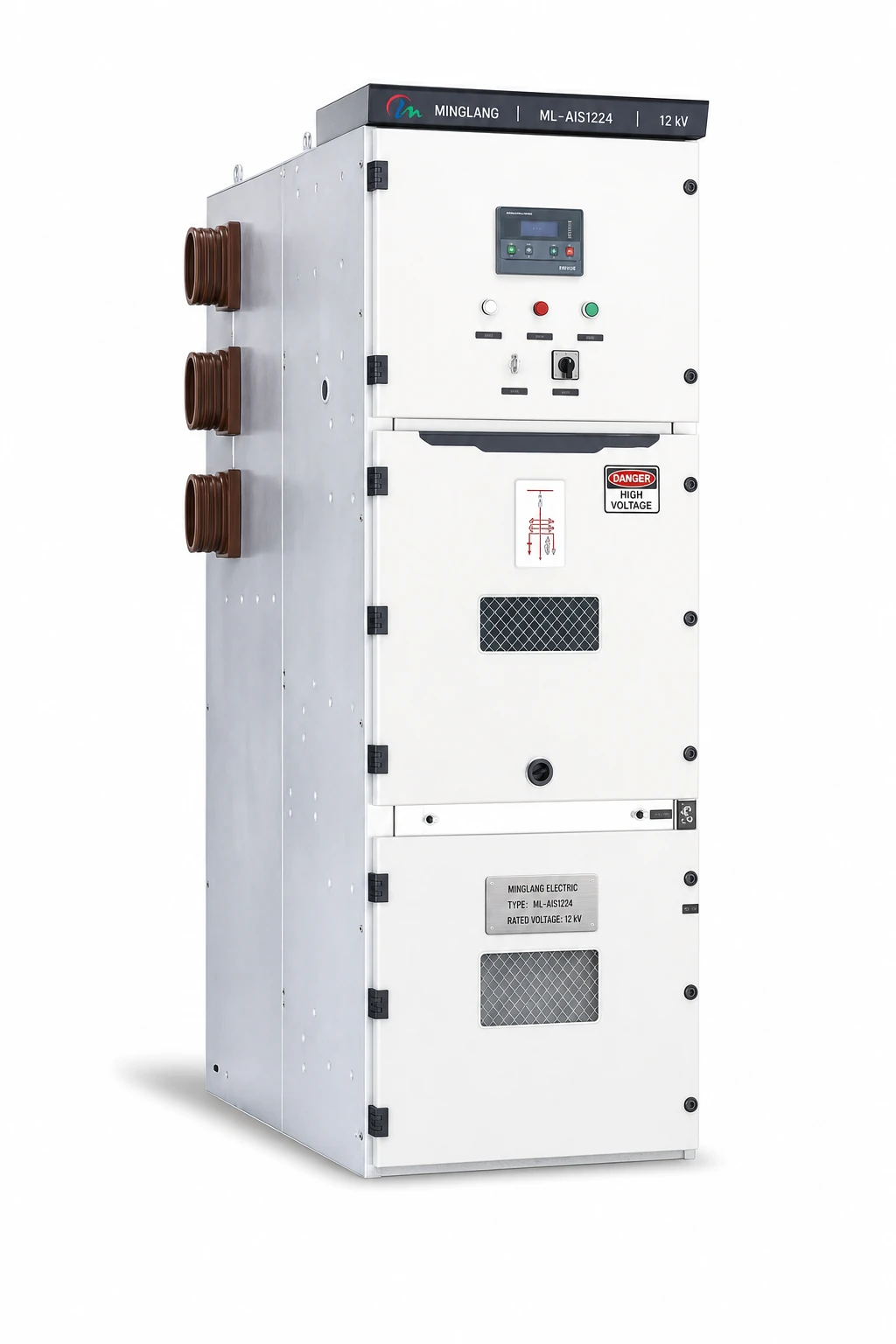
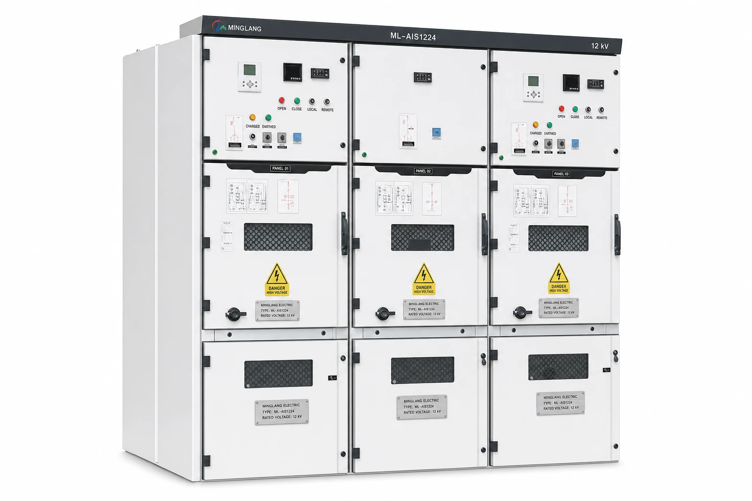
The public ML-AIS1224 product page lists IAC AFLR 31.5 kA/1 s for its documented 12 kV reference configuration. This is a catalogue reference for early selection. For a project offer, request confirmation that the available evidence applies to the proposed panel types, construction, ratings, end covers, installation arrangement and pressure-relief solution. Do not assume that the public reference covers every 12 kV or 24 kV configuration.
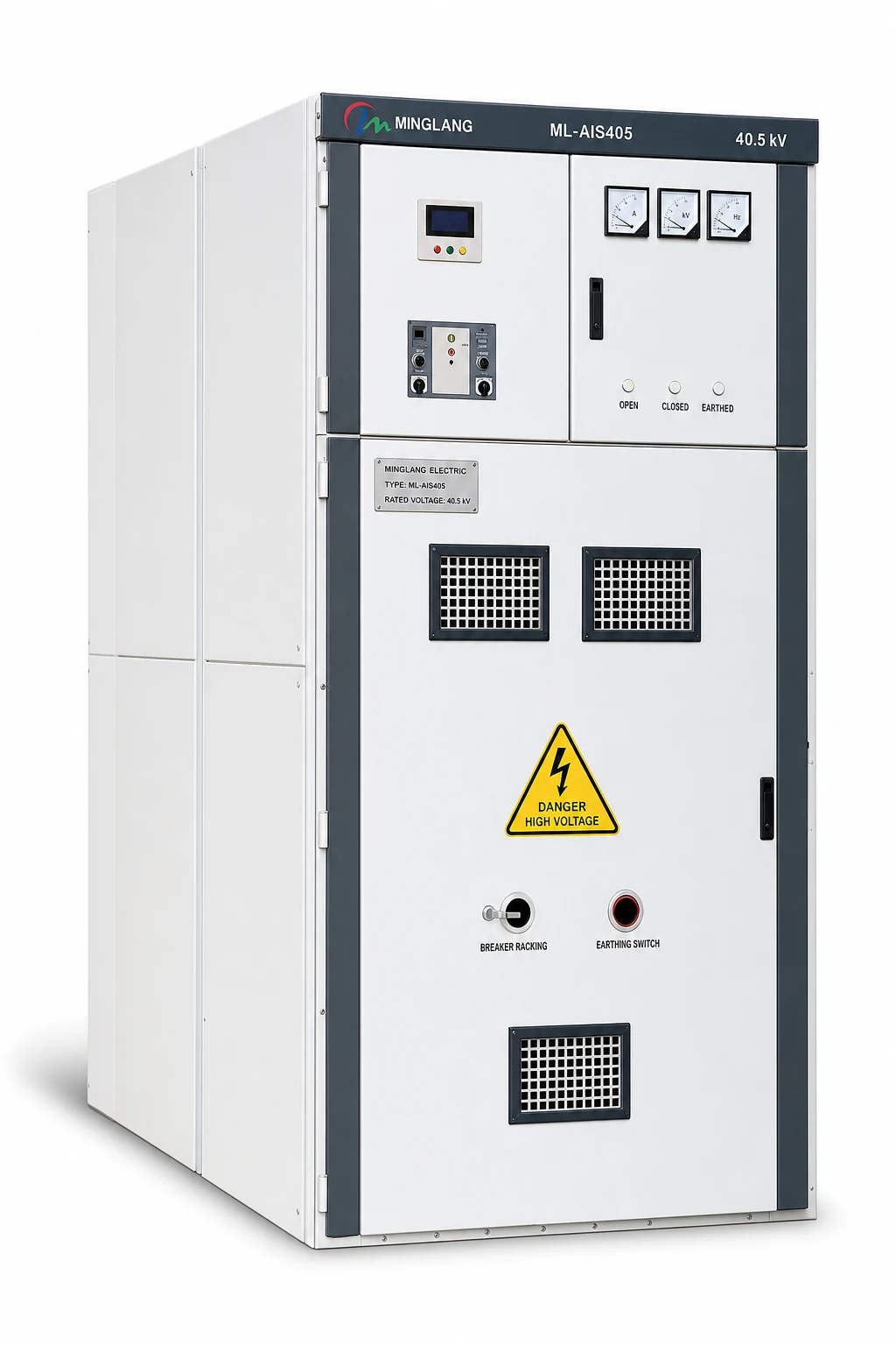
The ML-AIS405 product page presents a project-engineered 40.5 kV platform and a reference dimensional envelope. Its public reference data does not state an IAC rating. The project team should request the current configuration-specific document set and should not infer an internal-arc classification from the product family or from another voltage platform.
Buyer checklist before technical bid approval
- Full designation states IAC, accessibility type, accessible sides, current and duration.
- The specified IEC 62271-200 edition is identified.
- Fault current and total protection clearing time have been issued by the system designer.
- Every accessible side is marked on the room plan.
- Back-to-wall or free-standing installation matches the supplier’s verified arrangement.
- GA shows panel height, arc duct, flap movement and minimum clear height.
- Rear and side maintenance access remains practical.
- Hot gases terminate at a safe point and cannot enter a normal escape or working route.
- Civil designer has considered room pressure, openings, doors and penetrations.
- Test evidence is mapped to the offered lineup, ratings and construction.
- LSC and PM/PI are reviewed separately from IAC.
- Site arc-flash risk assessment, operating procedure and PPE requirements remain in the project safety scope.
Frequently asked questions
1. Is AFLR always better than AFL?
AFLR covers an additional accessible face: the rear. It is necessary when the rear can be approached. A verified AFL back-to-wall installation can be appropriate where rear access is permanently excluded. Selection should follow the room and operating arrangement.
2. Does a rear aisle behind a locked door require R?
Usually yes when authorized personnel may enter that aisle while the equipment is energized. A locked door controls who enters; it does not make the rear face physically inaccessible to authorized personnel.
3. Does IAC mean the switchgear is safe for live work without PPE?
No. IAC is a conditional assembly classification. Safe work practices, risk assessment, operating procedures, remote operation where appropriate and required PPE remain applicable.
4. Is IAC the same as an arc-flash study?
No. IAC is based on an internal-arc test of a defined switchgear assembly. An arc-flash study calculates or assesses site-specific worker exposure using the electrical system, protection operation, working distance and task conditions.
5. Must the IAC current equal the switchgear short-time withstand current?
Do not assume that they are equal. They are separate declared ratings and may have different durations. Compare both values with the project duties and read them separately in the test evidence and data sheet.
6. Can an exhaust duct be added after the switchgear is selected?
Only through a manufacturer-approved arrangement supported by the applicable design and evidence. Duct cross-section, bends, joints, supports and outlet conditions affect pressure and gas flow. An unverified site modification may invalidate the intended performance.
7. Does LSC2B-PM imply IAC AFLR?
No. LSC2B addresses service continuity and PM identifies metal partitions or shutters. The IAC designation must be stated and evidenced separately.
Send the room data before asking for an IAC selection
For a configuration review, send Minglang the switchgear-room plan and section, system fault level, maximum protection clearing time, authorized/public access conditions, accessible front/side/rear faces, and the proposed arc-exhaust route and outlet. With those inputs, the engineering team can prepare a project-specific GA and identify the product documents that require applicability review.
Source material
References
- IEC 62271-200:2021+AMD1:2024 CSV — official IEC publication page.
- ABB UniSafe 2.0 — IAC AFLR and gas-exhaust options.
- ABB ZX0.2 catalogue — wall-installed AFL and free-standing AFLR example.
- ABB Smarter Safety — passive, active and preventive arc-flash mitigation.
- Siemens NXAIR — IAC A FLR, LSC2B and PM product example.
- Schneider Electric MCSeT — applicable classifications and building-pressure boundary.
- Schneider Electric MCSeT — switchgear-room and pressure-relief requirements.