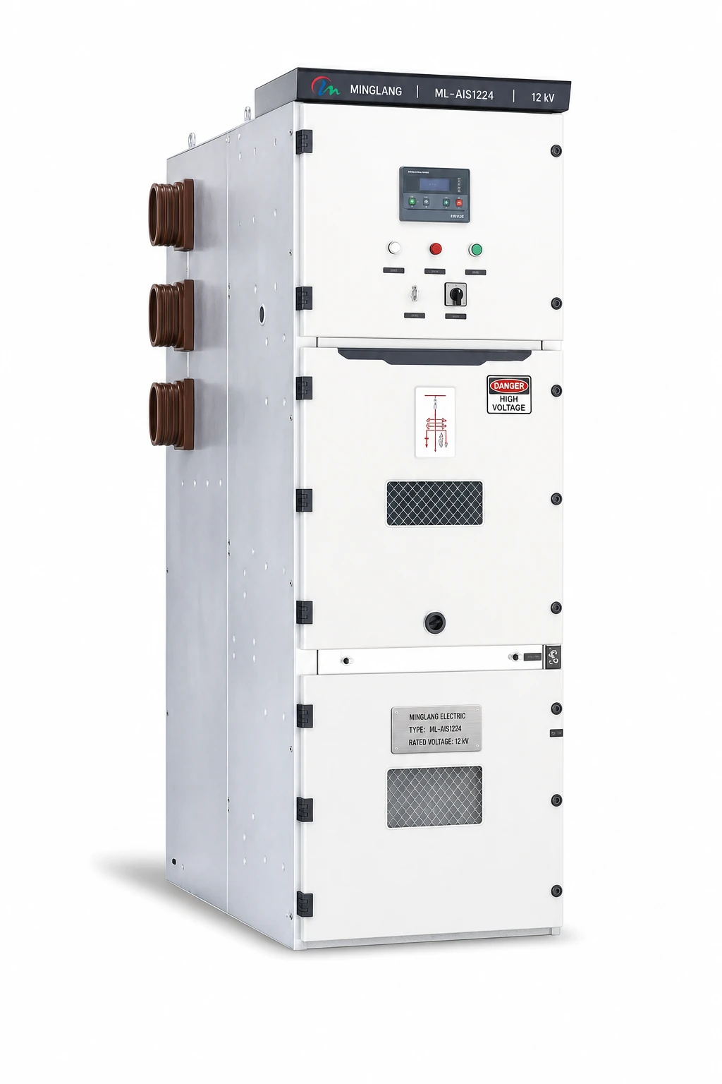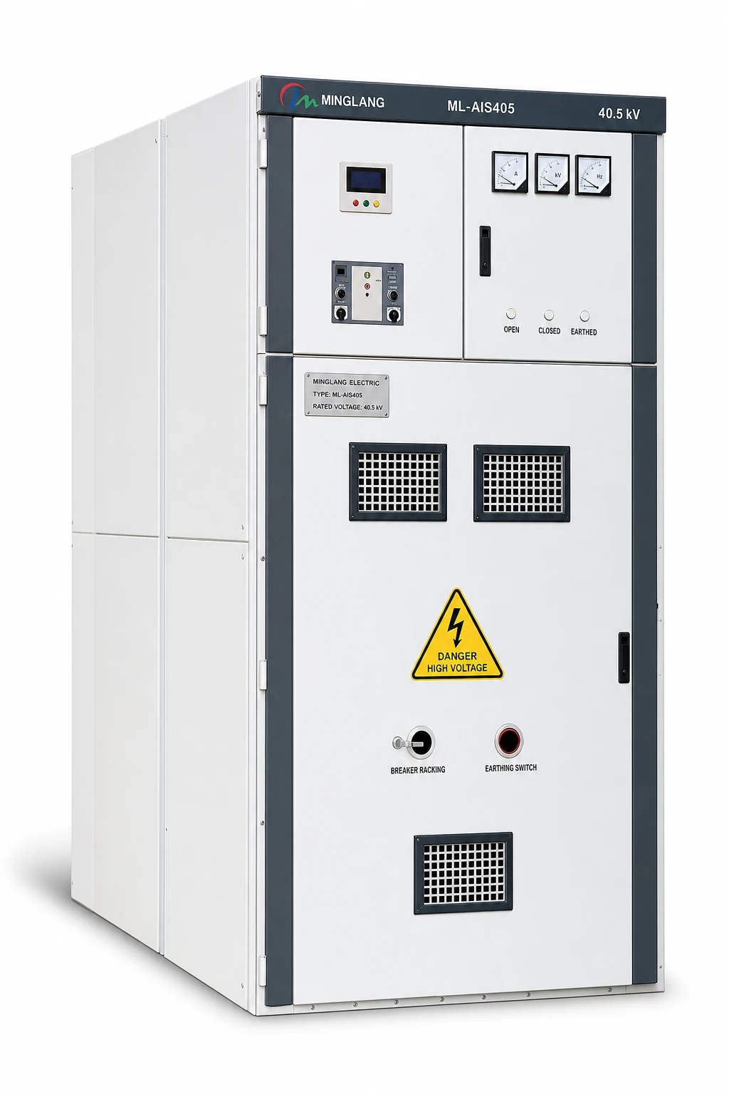
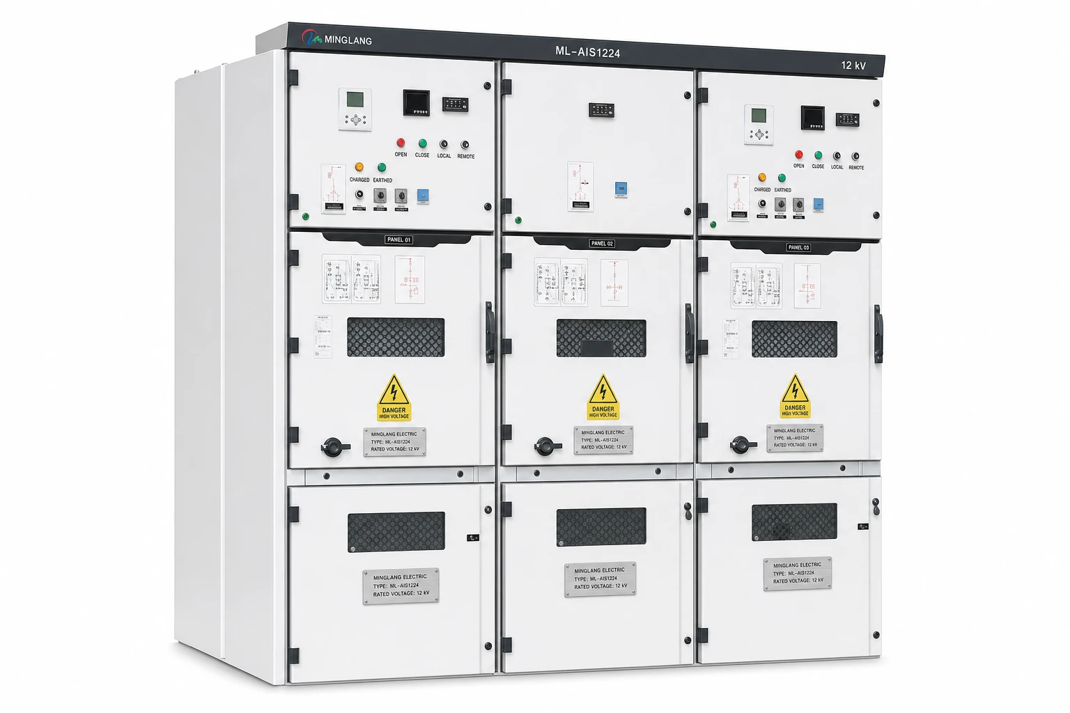
Two quotations marked 12 kV, 31.5 kA are comparable only after their complete technical duty and supply boundaries have been normalized. The headline values do not define rated current, fault duration, peak withstand, breaker duty, IEC 62271-200 classification, instrument transformers, protection, cable interfaces, tests, documents or services. Compare each offer against one project-specific compliance schedule, record every deviation and price all exclusions before selecting the lower evaluated cost.
Why the headline rating is insufficient
IEC 62271-200:2021+A1:2024 covers prefabricated metal-enclosed AC switchgear assemblies above 1 kV and up to 52 kV. The standard provides a framework; “12 kV, 31.5 kA” remains an incomplete purchase specification. The first value normally identifies equipment rated voltage. The second may refer to assembly short-time withstand current, breaker short-circuit breaking current, or both. State each duty separately. Treat blank bid fields as “not stated” until confirmed in writing.
Core comparison table
Use the table below as a minimum bid-evaluation structure. The project specification may require additional fields.
| Review area | Information that must be stated | Why it can change price or risk |
|---|---|---|
| System and site | System/equipment voltage, frequency, earthing, indoor/outdoor duty, temperature, altitude, pollution, seismic duty | Affects insulation, temperature rise, enclosure and derating |
| Main ratings | Busbar/feeder current; short-time current and duration; peak current | “31.5 kA” without duration and peak duty is incomplete |
| Insulation | Power-frequency and lightning impulse withstand levels | Confirms suitability for network and site |
| Circuit breaker | Current, breaking/making duties, sequence, specified endurance classes, mechanism and control voltage | Changes duty, maintenance and lifecycle |
| Construction | Fixed/withdrawable, LSC, partition, IP, IAC, arc exhaust, dimensions | Affects continuity, access and room design |
| CTs and VTs | Ratios, cores/windings, burden, classes, protection performance and mounting | Must match metering and protection |
| Protection | Relay/model, functions, I/O, records, protocol and files | A relay model does not define integration scope |
| Auxiliary system | Supplies, coils, supervision, heaters, indications and interlocks | Omissions often become variations |
| Interfaces | Cable data, entry, terminations, gland plates, earthing, sensors and bus duct | Determines geometry and accessory scope |
| Tests/documents | Type-test evidence, routine tests, FAT, witness points, drawings and formats | Routine tests do not automatically include project FAT |
| Commercial scope | Spares, tools, packing, supervision, commissioning, warranty and exclusions | Determines installed and evaluated cost |
1. Normalize the electrical ratings first
Rated voltage and insulation duty
Confirm system nominal voltage, switchgear rated voltage, insulation levels, frequency and neutral-earthing arrangement. Temperature and altitude affect current-carrying or dielectric performance. Condensation, dust, salt, corrosive gases and seismic duty may require design measures. Verify catalog ratings against the declared service conditions.
Current, short-time current and peak current
Record rated normal current for each functional unit and the main busbar; incomers, couplers and outgoing feeders may differ.
For fault duty, record at least:
- rated short-time withstand current and duration for the assembly;
- rated peak withstand current;
- circuit-breaker rated short-circuit breaking current;
- circuit-breaker rated short-circuit making current; and
- earthing-switch making duty where the project requires a make-proof earthing switch.
IEC 62271-100:2021+A1:2024 covers AC circuit breakers above 1 kV. Both breaker duty and assembly withstand must meet the project requirement.
2. Compare the switching device, not just its brand
Specify breaker type, voltage, current, breaking/making ratings, operating sequence, required endurance classes, mechanism, coil voltages, auxiliary contacts and interlocks. For fixed or withdrawable designs, confirm positions, shutters, racking, earthing and permissible closed-door operations. Schedule options such as remote racking or duplicate trip coils. Verify that the offered breaker-panel combination is within the supplier's stated assembly evidence; a component report covers only the component tested.
3. Define CTs and VTs from the protection and metering design
IEC 61869-2:2012 applies to inductive current transformers, and IEC 61869-3:2011 applies to inductive voltage transformers. A quotation stating only “CT and VT included” cannot be evaluated technically.
For each CT, specify ratios, cores, metering/protection classes, burden, protection performance, short-time thermal and dynamic current, and terminals. Consider relay and lead burden together. Identify available taps on multi-ratio CTs.
For each VT, define primary/secondary voltages, winding connections, classes, burdens, residual-voltage winding, fuses, secondary protection and isolation. Address earthing and specified ferroresonance mitigation. Instrument-transformer size, core count and withdrawal arrangement can change the panel layout.
4. Read LSC, partition and IAC designations as operating conditions
Copy IEC 62271-200 classifications in full from the proposed, evidenced configuration.
- Loss of service continuity (LSC) concerns what must be de-energized when an accessible high-voltage compartment is opened. Ask the bidder to explain the practical isolation condition for the breaker, cable and busbar compartments, then verify that explanation against the declared LSC category.
- Partition class PM or PI identifies whether partitions and shutters between accessible and live high-voltage parts are metallic or include insulating material, as defined by the standard.
- Internal arc classification (IAC) must include accessibility type, accessible sides, test current and arc duration. “Arc resistant” without the full designation and arrangement is not sufficient.
For example, IAC A FLR 31.5 kA 1 s identifies authorized-personnel accessibility, front/lateral/rear sides, current and duration. Check it against panel construction, installation, arc duct, clearances and relief path. IEC TR 62271-307:2024 gives guidance when a supplier proposes extending type-test validity to another enclosed-switchgear configuration.
Official product information shows the distinction: ABB publishes UniGear ZS1 as LSC2B-PM and A-FLR; Schneider Electric identifies EasySet MV as LSC2B-PM and IAC as an optional qualification. Each offered product therefore needs its own full declaration and evidence.
5. Specify protection, control and communication by function
List protection functions, setting groups, records, measurements, logic, I/O, trip outputs, arc inputs and time synchronization. “Microprocessor relay with IEC 61850” remains incomplete.
Define protocol edition, architecture, ports, redundancy, synchronization, gateway responsibility and engineering files. IEC 61850-6:2009+A1:2018+A2:2024 addresses the configuration description language related to IED communication. Protocol support alone does not include signal mapping, network engineering, testing or SCL-file delivery.
The control schedule should also state:
- auxiliary supply voltage and permitted range;
- trip and close coil arrangement;
- local/remote selection and command hierarchy;
- anti-pumping and trip-circuit supervision;
- electrical and mechanical interlocking philosophy;
- mimic, indications, alarms and terminal allocation; and
- space, terminals and wiring for future signals.
6. Resolve cable and room interfaces before award
Issue one cable schedule covering material, insulation, cross-section, runs per phase, diameter, screen earthing, termination, bending radius and entry direction.
Allocate lugs, terminations, glands, clamps, gland plates, surge arresters and earthing hardware. Confirm zero-sequence CT location and that required cores/screens can pass through it.
Compare dimensions, clearances, foundations, floor openings, lifting route, arc duct, exhaust outlet and transport sections. Include any rear-access requirement.
7. Separate type-test evidence, routine tests and project FAT
These three items serve different purposes:
- Type-test evidence supports a defined design. Review the standard edition, test object, ratings, components, laboratory, scope and proposed extension of validity.
- Routine tests apply to manufactured equipment under the product standard and agreed specification.
- FAT is the project's contractual inspection and test program. It may add witnessed routine tests and functional checks of protection, controls, interlocks, communication and interfaces.
State witness/hold points, notice, records, relay injection, communication simulation, test-equipment certificates and retest rules. Agree how provisional settings will be tested and later verified.
Set a dated document register covering drawings, schematics, terminal plans, bills of material, foundation/cable interfaces, protection data, test records, FAT procedures, manuals, packing lists and required editable files.
8. Price the complete delivery scope
Normalize commissioning and operational spares, handling equipment, earthing devices, test plugs, tools, lifting accessories and consumables.
Confirm packing class, moisture protection, package limits, shipment splits and storage duration. Allocate supervision, commissioning, relay/SCADA support, training and travel. Compare warranty start, duration, remedy and spare-parts support location.
Illustrative comparison: identical headline, different delivery
The following example is illustrative only. It is not a record of an actual project, product or quotation.
| Item | Hypothetical Offer A | Hypothetical Offer B | Evaluation action |
|---|---|---|---|
| Headline rating | 12 kV, 31.5 kA | 12 kV, 31.5 kA | Still not comparable |
| Short-time duty | 31.5 kA for 3 s; peak stated | 31.5 kA for 1 s; peak not stated | Check system clearing time and request peak rating |
| Construction | Withdrawable; LSC2B-PM | Withdrawable; LSC not stated | Request full IEC 62271-200 classification and evidence |
| IAC | A FLR 31.5 kA 1 s, duct included | “Internal arc tested”; exhaust parts excluded | Request full designation, arrangement and exhaust scope |
| CTs | Ratios, cores, classes and burdens scheduled | CT ratio stated; cores/classes pending | Obtain complete CT schedule before acceptance |
| Relay | Functions, I/O and protocol files listed | Model identified; engineering excluded | Price missing engineering and confirm functions |
| Cable scope | Bottom entry, two cables/phase; clamps and gland plates included | One cable/phase assumed; terminations excluded | Verify physical capacity and normalize accessories |
| FAT and documents | Witnessed routine and project functional tests; document register included | Routine tests; FAT and editable files optional | Add options and schedule impact to evaluated price |
Offer A is not automatically the correct choice. Offer B may be adequate if the project requires only 1 s duty and a different access or service-continuity arrangement. The decision becomes defensible only after both bidders respond to the same fields and all accepted deviations are recorded.
Buyer checklist before commercial comparison
- Issue one controlled single-line diagram and equipment schedule to every bidder.
- State the applicable standard editions and project-specific amendments.
- Provide fault current, required duration, peak duty and protection clearing assumptions.
- Record busbar and feeder continuous-current ratings separately.
- Confirm breaker, earthing-switch, CT and VT duties in scheduled fields.
- Require the full LSC, partition and IAC designations for the offered configuration.
- Define relay functions, I/O, communication architecture and engineering deliverables.
- Issue cable data, room layout, access, foundation and arc-exhaust requirements.
- Separate type-test evidence, routine tests and project FAT in the bid form.
- Compare document registers, spares, packing, supervision, commissioning and warranty.
- Log every deviation, qualification, assumption and exclusion.
- Calculate the normalized evaluated price before comparing delivery time and commercial terms.
Frequently asked questions
Does 12 kV, 31.5 kA define the switchgear short-circuit rating completely?
No. The quotation should distinguish assembly short-time withstand current, its duration, peak withstand current, breaker breaking current and breaker making current. The earthing-switch making duty may also be relevant.
Is a 3-second rating always better than a 1-second rating?
It provides a different withstand duration, but the project requirement must come from the protection clearing time, network study and specification. A higher duration can add cost and does not correct deficiencies elsewhere in the design.
Can two LSC2B switchboards be treated as equivalent?
Not without further review. Compare partition class, IAC designation, access arrangement, switching-device design, cable isolation conditions, interlocks and the configuration covered by test evidence.
Is IEC 61850 support in the relay enough for SCADA integration?
No. The project still needs an agreed architecture, signal list, data model, network and time-synchronization requirements, engineering responsibility, configuration files and integration tests.
Does a circuit-breaker test report cover the complete switchgear panel?
No. A breaker is one component. The complete metal-enclosed assembly has its own requirements and evidence under IEC 62271-200. The purchaser should also verify that the offered breaker-panel combination is within the evidence supplied for the assembly.
Is FAT included when a bidder states that routine tests will be performed?
Only if the quotation and inspection plan say so. Routine tests follow the applicable standard and specification. A witnessed, project-specific FAT can include additional functional, protection, communication and document checks and must be defined commercially.
What should be compared after technical normalization?
Compare the evaluated price, delivery schedule, approved deviations, document program, warranty, spare-parts support and site-service scope. Keep the final compliance schedule as a contract attachment.
Request a project-specific comparison
For a technical review or quotation, provide the single-line diagram (SLD), equipment schedule, site conditions, applicable standards and required document list. These inputs allow the proposed ratings, construction, protection, interfaces, tests and supply boundaries to be checked against one controlled project basis.
Source material
References
- IEC, IEC 62271-200:2021+AMD1:2024 CSV — AC metal-enclosed switchgear and controlgear.
- IEC, IEC 62271-1:2017+AMD1:2021 CSV — Common specifications for AC switchgear and controlgear.
- IEC, IEC 62271-100:2021+AMD1:2024 CSV — Alternating-current circuit-breakers.
- IEC, IEC 61869-2:2012 — Additional requirements for current transformers.
- IEC, IEC 61869-3:2011 — Additional requirements for inductive voltage transformers.
- IEC, IEC 61850-6:2009+AMD1:2018+AMD2:2024 CSV — Configuration description language for communication in electrical substations related to IEDs.
- IEC, IEC TR 62271-307:2024 — Guidance for extending the validity of type tests of enclosed switchgear and controlgear.
- ABB, UniGear ZS1 air-insulated switchgear — official product information.
- Schneider Electric, EasySet MV user guide — applicable standards and classifications.
- Siemens, NXAIR air-insulated medium-voltage switchgear — official product information.